Rs485 To Ethernet Wiring Diagram
Cut off one of the rj45 plugs and strip the cable exposing the wires. Remember that pin 1 is on the left hand side of the rj45 connector with the clip at the rear.
55 Rs485 To Wiring Diagram Wiring Diagram Plan

In addition to the data wires it is worth considering whether to use a shielded cable (braid/foil) connected to signal earth.
Rs485 to ethernet wiring diagram. If you do not have a rs232 plug, you can also use pin 5, pin6, pin7 to connect as the left picture. Locate the rj45 cable that was shipped with your mt50 remote or if you are using a longer rj45 cable you will need that cable instead. The full and half duplex wiring diagrams are.
Connecting to a terminal block is recommended. The rs485 on this ethertrak gateway is isolated from its internal circuitry, local power source, and Rs485 (2) wiring type] to 0:
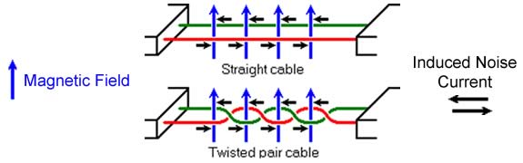
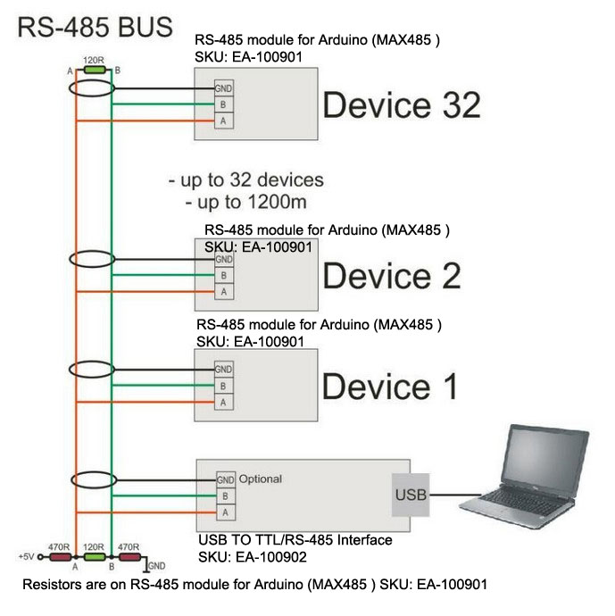
To transmit a logic 0, line b is low and line a is high. Figure 2 applies to several b&b converter models such as the 485drc, 485ldrc, 485ldrc9, and 4wsd9r. Rs485 communication wires should be a shielded twisted pair cable.
According to earlier, the traces in a rs485 wiring diagram represents wires. This is accomplished by encapsulating the. Rs 485 wiring diagram wiring diagram is a simplified enjoyable pictorial representation of an electrical circuit.
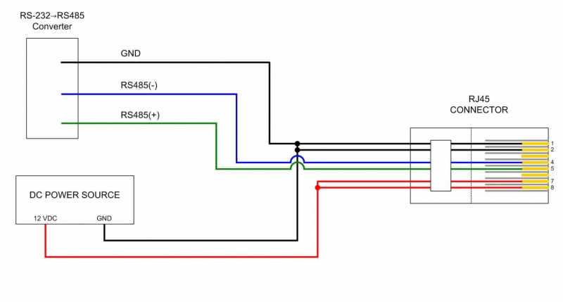
Occasionally, the cables will cross. Choose rs232 channel, take off rs485 channel g t connection method 1: Pin 5 → white and blue wire.
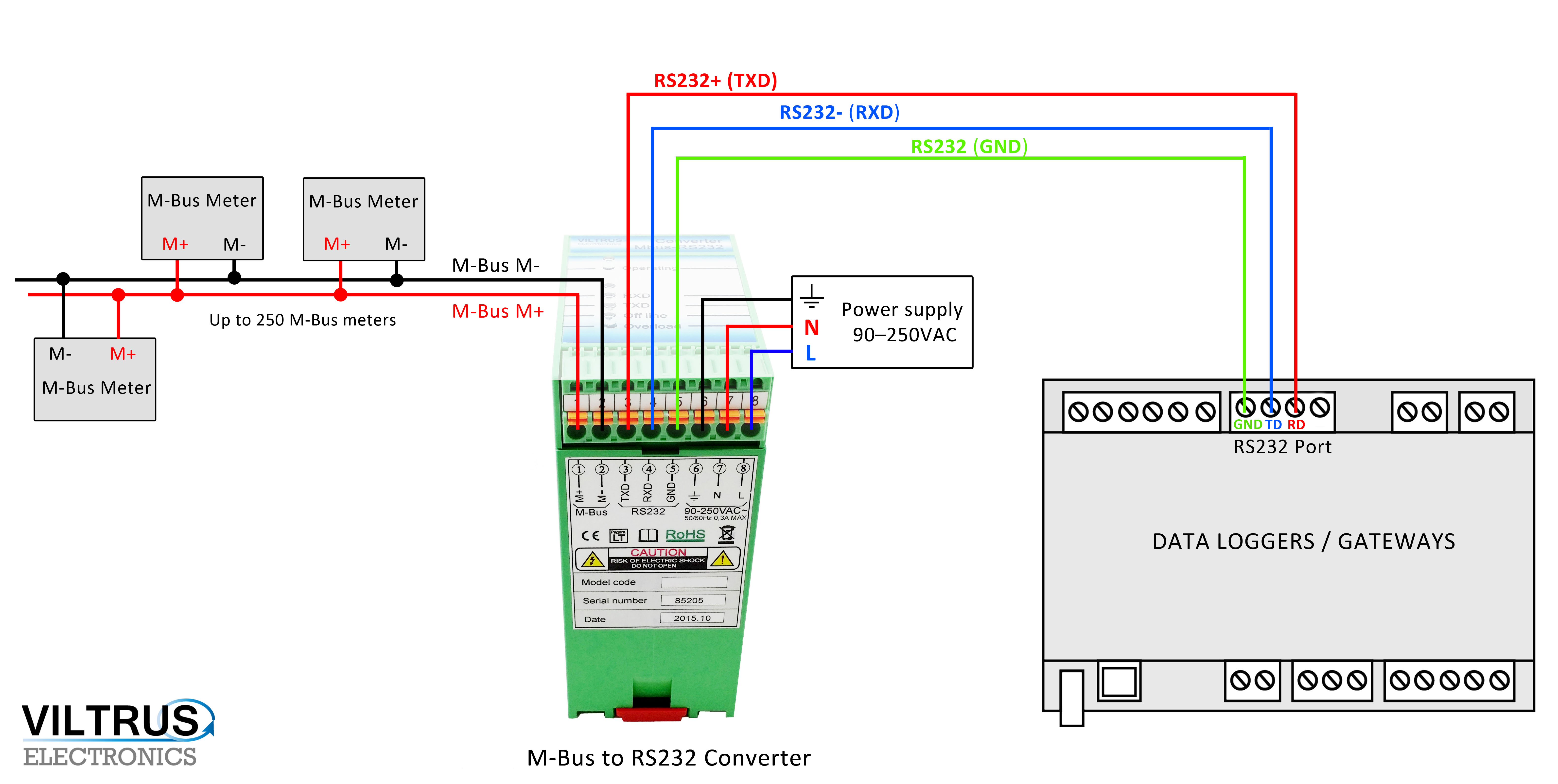
Wiring diagram of the serial rs232/rs485. Pin 3 → white and orange (receive +) wire. Pin 8 → brown wire.
Cat5e or cat6 ethernet cable recommended rs485 connection important notes: The diagram below shows the general wiring layout for a net2 plus acu. Certain ace have rs232 ports or configurable rs232/485 ports.
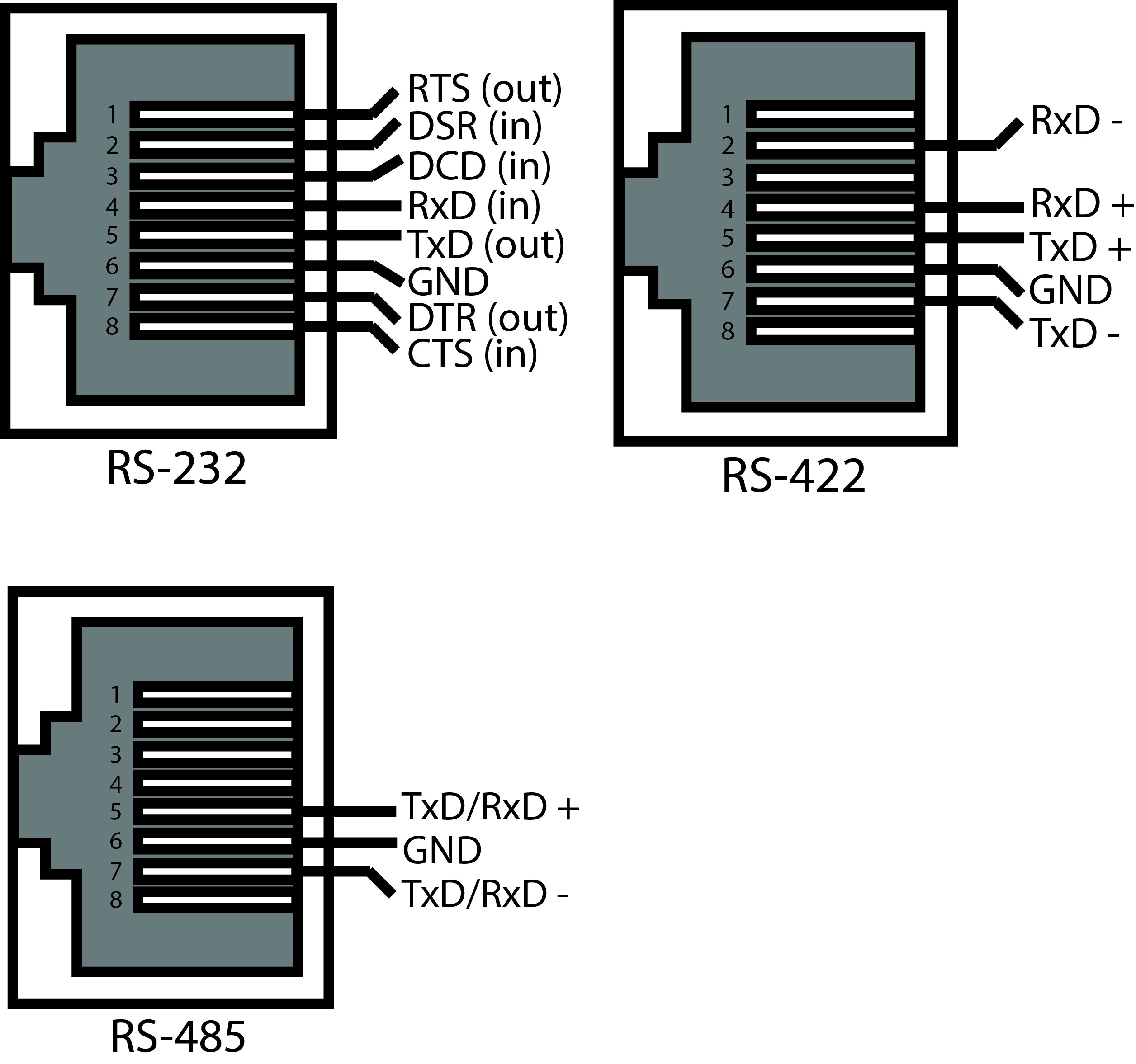
Figure 4 is a pin diagram for both 25 pin rs485 pinout half duplex and full duplex pinout connectors. Rs232 rs422 rs485 standard db connector pinout opengear help desk connector network engineer standard. There will be primary lines that are represented by l1, l2, l3, and so on.
But, it doesn’t imply link between the cables. The problem in point of fact is that all car is different. Rs485 (2) wiring type] to 1:
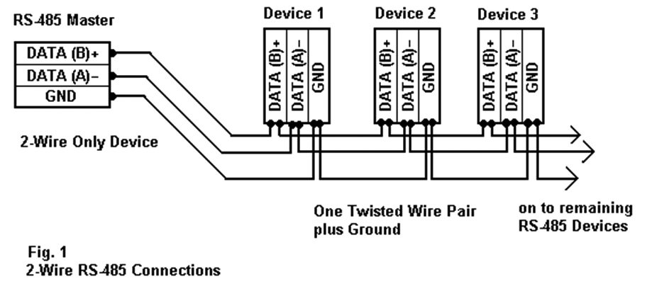
Figure below shows a single rs485 / rs422 signal being transmitted. Figure 3 is an rs485 wiring diagram for rs485 pinout db9 connectors. Rs485 to ethernet converters connect devices with rs485 serial interfaces to a local area network for transmission of serial data over wired or wireless ethernet.
They are also commonly used to interface cellular transceivers for internet of things applications and can be used in ascii communications. Pin 7 → white and brown wire. Injunction of 2 wires is generally indicated by black dot to the intersection of 2 lines.
You are advised to use a cat 5e outdoor shielded network cable with an outer diameter less than 9 mm (0.35 in.) and internal resistance not greater than 1.5 ohms/10 m (1.5 ohms/32.81 ft), as well as a shielded. By converting rs485 data signals into ethernet (tcp or udp) packets, and vice versa, they enable reliable data transmission to other devices or network server applications. It is recommended that the ground wire be connected to all stations to provide a common return.
Figure 3 is an rs485 wiring diagram for rs485 pinout db9 connectors. Pin 4 → blue wire. To transmit a logic 1, line b is high and line a is low.
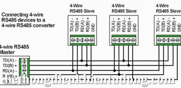
Subsequently aggravating to remove, replace or fix the wiring in an automobile, having an accurate and detailed rs485 to ethernet. The distances these signals are carried is greater due to differential signals. But note that txd and rxd have to cross connect.
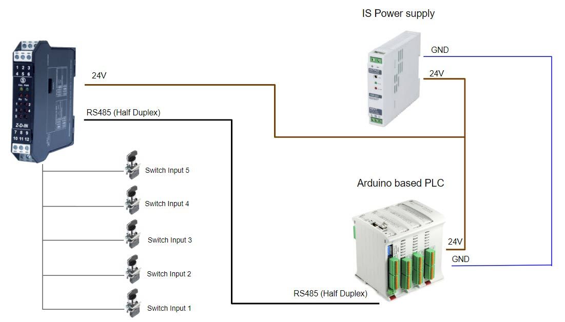
The advantage of this arrangement is that signals can be transmitted faster and over greater distances than is possible with a single wire. Rs485multiple driver communications rs485 is similar to rs422 upon which it is based. Power wiring diagram without backup battery with backup battery switching power supply ground ground switching power supply figure 15 figure 14.
The rs485 communications cable can connect to either a terminal block or an rj45 network port. Rj45 pinout diagram shows wiring for standard t568b t568a and crossover cable. Rs232 ports are commonly used for interfacing hmi and other devices through modbus rtu communications.
Ideally the two ends of the cable will have a termination resistor connected across the two wires and two powered resistors to bias the lines apart. Rs485 half duplex wiring diagram.
RS485 vs Which One is Most Used in Industry?
55 Rs485 To Wiring Diagram Wiring Diagram Plan
Rs485 To Rj45 Wiring Diagram Practical To Rj45 Wiring Diagram Rj11 Wiring Diagram Rs485 Pinout

Connecting RS485 4wire to 4wire Serial Data Communication by U.S. Converters LLC

Rs485 4 Wiring Diagram Complete Wiring Schemas
Rs485 Cable Color Code Colorpaints.co

Usb To Rs485 Wiring Diagram USB Wiring Diagram

RS485 Connections FAQ 研華科技 Advantech
Rs485 To Wiring Diagram Understanding Rs485 Wiring Connection Monitoring Software

RS485 pinout · Tuxotronic
55 Rs485 To Wiring Diagram Wiring Diagram Plan

[SY_4917] Rs485 Db9 4 Wiring Diagram Free Diagram

Rs485 Split Wiring Diagram
RS485Modules ArduinoInfo
Modbus Rs485 Wiring Diagram My Wiring DIagram
Rs485 To Wiring Diagram Understanding Rs485 Wiring Connection Monitoring Software

Rs485 Wiring Diagram — UNTPIKAPPS

Rs485 To Rj45 Wiring Diagram Professional Wiring Diagram Wiki Rs, Db9 Pinout Diagram

Rs485 To Wiring Diagram Understanding Rs485 Wiring Connection Monitoring Software
